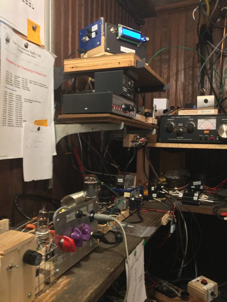
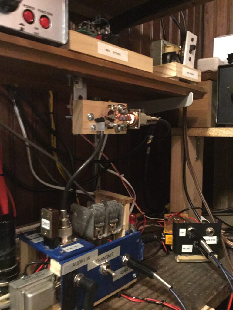
The photo above, worth its thousand words, shows the current state (6-10-2020) of my K9EID Pine Board Transmitter installation. At the top of the photo is the Super DDS (Direct Digital Synthesis) designed, and sold as a kit by N3ZI. To the left, moving down the shelf to the right, is the power supply, almost out of the shot except for the on-off switch and fuse, then the preamp, and, finally, the transmitter. In this shot, the filaments are lit, but the rig is not keyed up.
A glance along the front of this shelf, to the right of my morse code cq cheat sheet, is the ‘Keyall,’ the discreet component version, that lights up very brightly with each key down, and switches, by means of two fairly beefy transistors, pretty much any direct current/voltage. More on this in a bit.
More about this installation: the tube in the preamp is a 12AU7, not the 12AX7 called for in K9EID’s schematic. The preamp and transmitter are pretty straight forward and tolerant of tube substitutions. I’ve felt free to experiment. The 12AU7 (or 6201/12AT7) will not clip when driven by a line level device. This makes it easy to feed some repeating speech pattern to the preamp for testing. In the transmitter, the 6V6 modulator has been traded for a 6L6C. I have not put a meter across the B+ on either the 6L6 or the 6AG7 (oscillator and final) lately, but I assume the 6L6 is slumming and not swinging very hard. When the B+ hits the tube, it glows a nice blue, which reminds me that it is doing its thing. This particular 6L6 is a well-used Sylvania that I picked up at the Peoria Hamfest for about $15. Not a great tube for not a great price; I’m happy to put it to work in this circuit and enjoy its glow. Feeling sentimental about hamfests just now. They’ve all been cancelled in the onslaught of the pandemic.
Starting with the top shelf: My build of N3ZI’s Super DDS. According to QRZ.com, N3ZI is Doug Pongrance of Las Vegas, Nevada. His instructions for this kit warn that it is meant for expert builders. In general, my process through this build, and each phase of the ‘DDS as VFO’ project was guided by another ham/academic, Greg Latta, AA8V. His amateur radio-oriented website is a goldmine for DIY-inclined hams. His web presence covers his various interests, and it’s all refreshingly accomplished and worthwhile. A sort of index of that presence is found here. I gotta send him an email and report back. The document I worked through in constructing this VFO system is found here. To top it all off, Dr. Latta is also a musician. One has some hope that the dust from accomplished people like these will rub off to a certain extent. This is a priceless advantage of being a radio amateur and learning about radio.
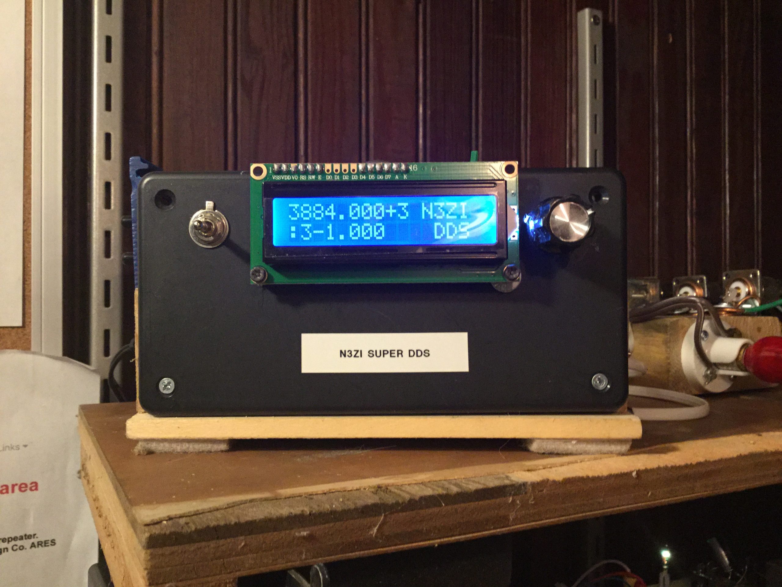
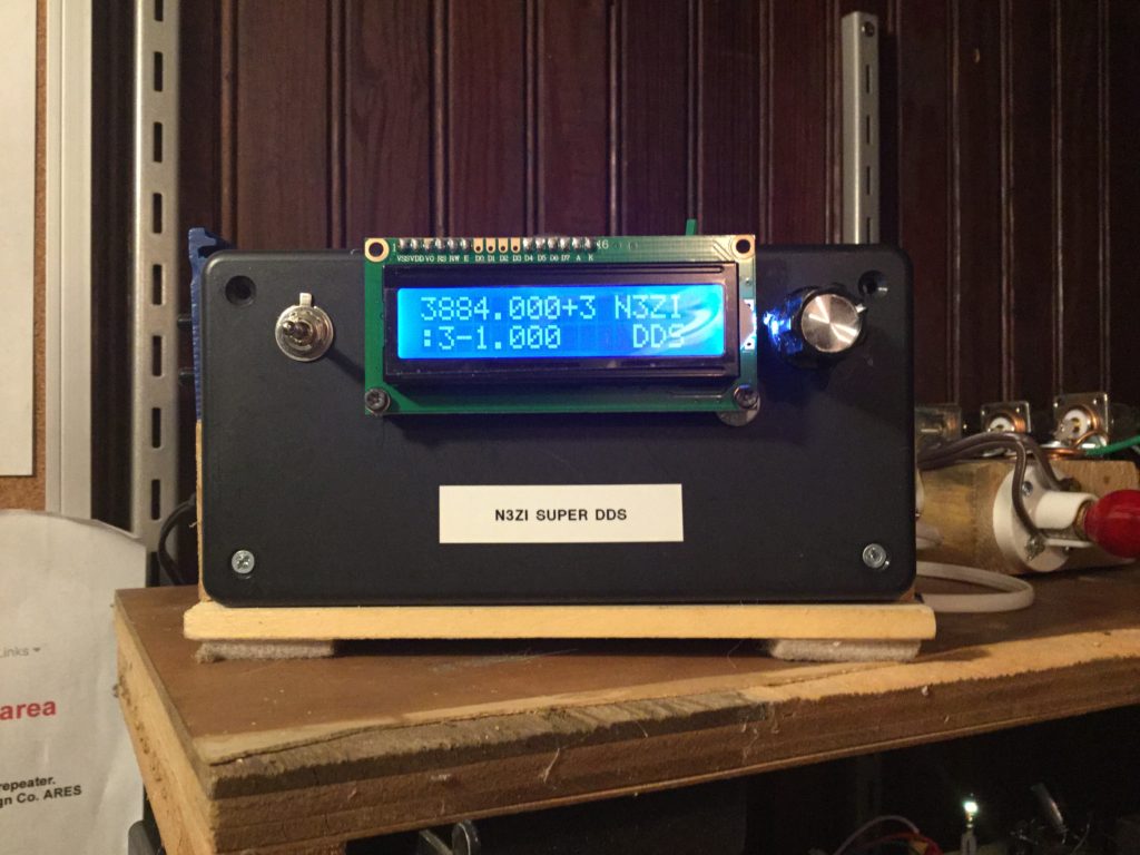
For me, the challenge of the DDS kit was getting the LCD working. AA8V suggested building for a more useful enclosure, which in my case meant something mounted on a block of wood. This meant bringing the LCD away from the board, where it could’ve easily been soldered in proper orientation to a header. The same was true of the switches. But the LED involves 12 pins, not 3. Keeping them straight, and coming up with a way of making good connections that were at the same time not permanent, because who knows when I’ll want to tear all of this apart and take a different tack, was what set me back a while. I confess, I fried my first LCD and had to wait for a slow boat from China to deliver another one. Another error that I sweated out: the failure to correctly orient the oscillator chip when i gleefully soldered it in. I was lucky. This error was not fatal. Once the LCD was functional, I was able to confirm that the DDS performed as expected. I programmed the DDS with a few memories representing frequencies I may use, and learned how to set the RIT (receiver increment tuning) offset. Interfacing with the DDS via other components in the AA8V system was simply a matter of identifying the correct pins on the board and giving them what they wanted to accomplish the desired function. In the case of the RIT function, the goal of which is to move the VFO off the transmit frequency in receive mode, a transistor switch is employed to be switched by the keyer. In receive, the DDS is set at some functional, arbitrary offset. As one can see in the photo, I am 1 MHz below the desired transmit frequency. Upon the key-up, the key triggers the transistor, the transistor pulls the RIT circuit to ground, and the the VFO goes to the transmit frequency. Works like a charm. As one can see from a glance at the DDS LCD, the frequency is displayed in KHz. (3884 KHz = 3.884 MHz.) Key the rig to transmit, and this becomes 3.885 MHz.
The switch to the left of the LCD is a DPTT momentary contact switch that scrolls up or down through the memories. The knob to the right is for tuning and, by pushing in on it, changing to various modes. As with all such diabolical contemporary contrivances, a combination of pushes, twists, and up or down presses accomplish the DDS’ various programming, so long as one can find the manual and bone up on what does what. One can certainly just turn the knob and arrive at whatever frequency is desired. The RIT difference is stored in non-volatile memory, as is the last frequency one paused at. There are a total of 12 memories, 10 that are numbered and 2 that are lettered, selectable with yet another switch. I buried this switch out of the way, back by the guts. These are likely to be guts I will soon revisit.
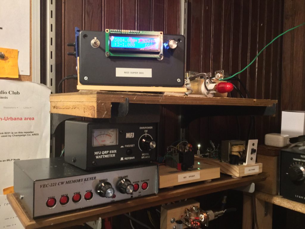
Bottom Shelf: Vectronics CW Keyer, Wattmeter, Relays, Power Supply
Moving to the next shelf down, there are a few basic pieces of the installation. To the right in this photo is the power supply. Nothing really special, it powers the DDS above, the relays to the left of it, and the buffer amp, which sits behind the DDS on top of the pine board in the above mentioned guts. That dad-gummed buffer amp was the component that stumped me for quite awhile. I built the simple circuit with two amplifying transistors, a pair of 2N2222As, as called for in AA8V’s documentation. It was supposed to take the small voltage put out by the DDS and boost it by a factor of ten or so. The DDS was putting out 250 millivolts, more or less, on the scope. It generated a decent, stable sine wave, as it was supposed to do. But for some reason, the DDS failed to show up on the DMM (digital multi-meter), set to auto range for AC volts. That was the hint I failed to take. Then, the buffer amp, built quickly on a scrap of old perf board, also failed to make any indication on the meter, and, what was worse, when tested on the oscilloscope, it was putting out the same low voltage as the un-amplified DDS, only now, the sine wave was, er… not sinusoidal. It was a noisy mess. OK, then. Perhaps I built it wrong. Checked it. Found an error or two. But the results were still foobar. Took it apart. Now, the two transistors tested bad. Perhaps, in unsoldering them, I killed them with too much heat. Now chastened, I built the circuit on a small breadboard. Again, I did not get the output I expected. I had a poor sine wave on the scope, and a low or peculiar voltage reading on the meter. I ordered a buffer amp kit from yet another DIY oriented amateur: WA1FFL. His write-up in the CQ magazine looked promising. His Haggerty Radio Company website offered a kit. Not to mention another DDS. I did not order his DDS. I was happy with the one I had built, and at $145, WA1FFL’s was not going to be good for my already expanding budget. I did order the buffer amp kit. It arrived, I built it. It included the step-up transformer, so I had high hopes of saving a step. It proved to be a very nice board, and I had no apparent trouble winding the toroid 1-2 transformer. I optimistically fitted it to the enclosure next to the Super DDS. On the meter, it gave a peculiar indication: the voltage leapt up from zero promising everything, but then fell back to zero delivering nothing. And the sine wave on the scope… another disappointingly noisy waveform. And, on the scope, not much more than the voltage of an induced hum. All very disappointing!
Is it possible that my readings were wrong from the outset? Looking into measuring high frequency voltages on DMMs and oscilloscopes, I soon learned that, unlike audio, RF measurement has a whole range of peculiarities. Meanwhile, the 3rd and final buffer amp product showed up. This last one was not from a ham, but rather from St. Helena, California. The DDS VFO Amplifier had this to say about itself on Ebay: “Is the output of your DDS VFO not quite enough to drive a vintage transmitter? This tiny two stage amplifier will provide apx (sic) 10X voltage at 12v. Ideal for older transmitters or other applications requiring more output than a DDS can deliver alone. Output is flat to just over 14 Mhz. Operates from approximately 9 to 15 VDC and provides a nominal 200 ohm load for common AD9850 DDS modules. Screw terminals for DC and .100 spaced solder holes for RF I/O. Now with Free USPS shipping to USA! Canada will be calculated as first class mail at check out. We are fully operational and shipping on schedule.” The price? $15. By the time it showed up, I had boned up on testing. This buffer amp, requiring NO building, and made with all surface mount components, is tiny. It put out a beautiful sine wave with the proper scope probe, so I slapped it in the enclosure and…
… tried it out on the transmitter. At long last, I now had a carrier wave. The carrier was a bit below the level of that generated by the crystal, so I went further and wound the toroid. The amp alone was indeed swinging 2 volts at 3.885 MHz, and this is indeed 10 times 200 millivolts, the approximate output of the DDS. The toroid successfully gets the voltage up to 4 volts, which gives me a more robust carrier. Success at last. I’m sure I’ll revisit those other amps that most likely perform better than I thought.
Let’s take a look at the rest of the install…
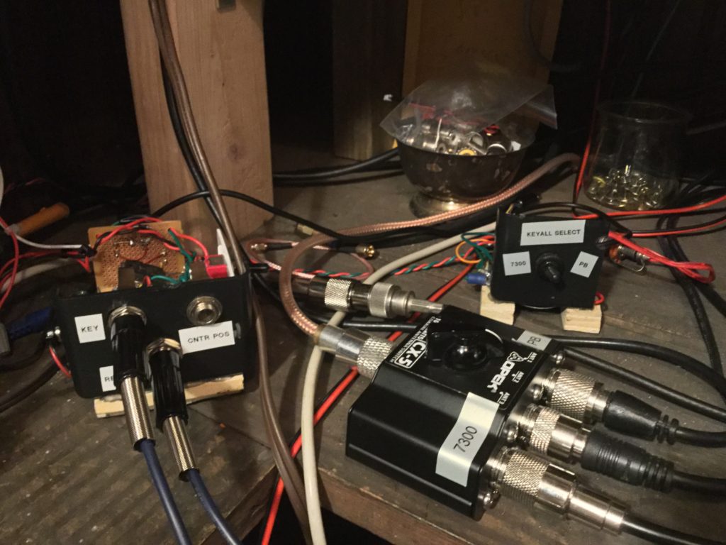
Above, on either side of the antenna selector switch, are the keying amplifier and the Keyall selector. The Keyall, mentioned above, is sold as a kit, and is the product of Chuck Olsen, WB9KZY. His online sales operation is called Jackson Harbor Press, and does business in Washington Island, Wisconsin. The version I built is called the Keyall Discreet, because it is made of discreet components, as opposed to integrated circuits (ICs). As noted, the majority of the components are LEDs which both drop the voltage and create a flash of green and red light with each key down event. It’s the transistors that handle the voltage, and in the pine board transmitter context , they serve to ground the cathode on keydown. This circuit is selectable on the pine board’s top panel. (Shall I refer to it as the dashboard? Why not?) The selector switches the key on and key offs to the Icom 7300, which is quite capable of CW without really needing all the muscle the Keyall provides.
Left of the antenna switch is the “Keying Amp.” This takes the switching action of the key, below, and manipulates it to activate both the transmitter and to pull the VFO up to frequency for transmit.
AA8V’s instructions called for measuring the voltage at the key. Well, since I was following the last thoughts of Heil & Company on the PBP, I had created the relay driven transmit / receive switch that shifts the antenna from the receiver to the transmitter and shorts the receiver when the relay is activated. This, by the way, is not the same as key down from the CW perspective. It is not even partial break in, at least not so far… The voltage that operated that relay coil, as per Heil’s specs, is 110 Volt line voltage. So to answer the question what voltage is “on the key,” I have had to say ‘household voltage (and current).’ So I put a relay in back of the keying amp board that switched that juice on and off.
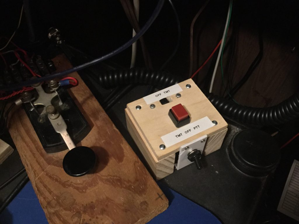
The selectable pair of switches above is intended to activate the transmitter, either as a switch for CW, or as a ‘push to talk’ (PTT) for AM phone.
And that’s the rig. Except… (Stay tuned for part 2… “Results… and Unintended Consequences.”)