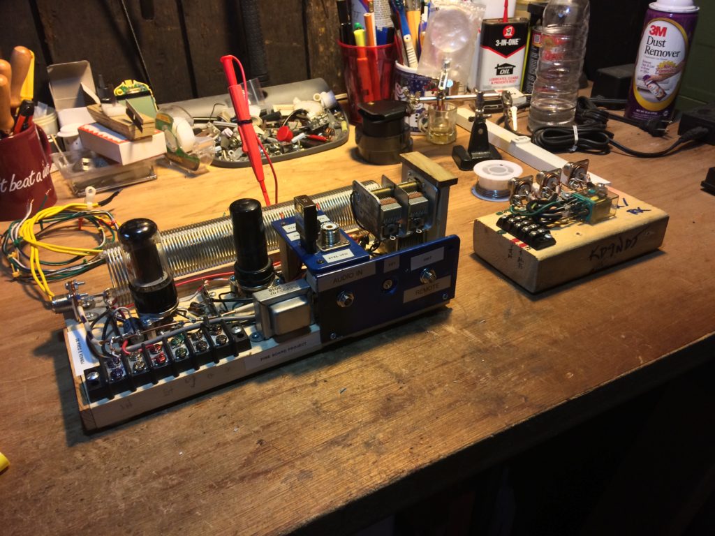
With the DDS VFO up and running, transmitting through a dummy load was the next step. The signal was modulated, but there was a lot of distortion and noise. The noise sounded like something out of Frankenstein’s lab: a snapping and arcing sound that was not antenna bound. The sound of my program, a loop of an 80 meter CQ call by yours truly, was copyable, but a bit distorted. RF in the shack?
This had been a problem on the Wellness Net lately, and had been pointed out by net control when, early on, I keyed up on the net. In that situation, I was using the Icom 7300 in Single Sideband Mode. (SSB.) I did some reading and re-organized the RF ground in my operating position. When I next heard “RF on my audio,” I went after that with ferrite on the mic line. Was this a similar issue? Did the Pineboard have an RF problem? If so, it was situational and a result of some feature of the install. The transmitter had performed well early on, and recently again, on the bench.
I found a pretty snarky article on “RF in the shack” that shook loose a few assumptions about the phenomenon. The two salient points: there’d better be some RF in your shack if your antenna system is working as intended. (If you’re getting RF burns, etc., yeah… you have a problem.) And the problematic phenomena are not dependent on grounding. (I found this last assertion contrary to most of my reading on the topic, and fairly radical. Most treatises distinguish between DC and RF grounding.)
Taking a more empirical tack for a change (for me, a method of last resort), I pondered my problem, and, in the spirit of W0LEV’s article cited above, thought about what it was not. It was not, at long last, the Heathkit VFO. That unit may well be in better shape than I had thought. Also, the problem is present when the crystal is used. My transmitter is now vfo/crystal selectable. It is not a grounding problem. The whole rig shares a ground with the earth ground, which is now an effective RF and DC ground. It is not RF on the audio, because the problem exists with no modulation, no connection of the preamp, and with the audio input shorted. The problem has to do with the installation, and with features that have not migrated when the transmitter has been on the bench and off the shelf in the operating position.
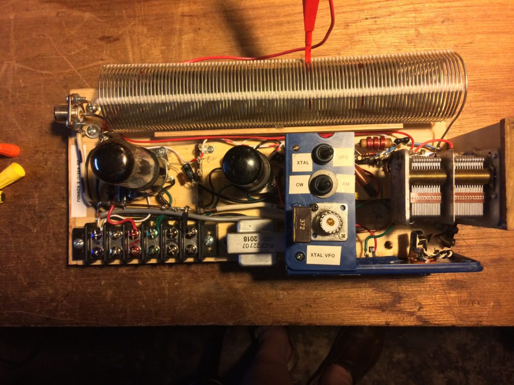
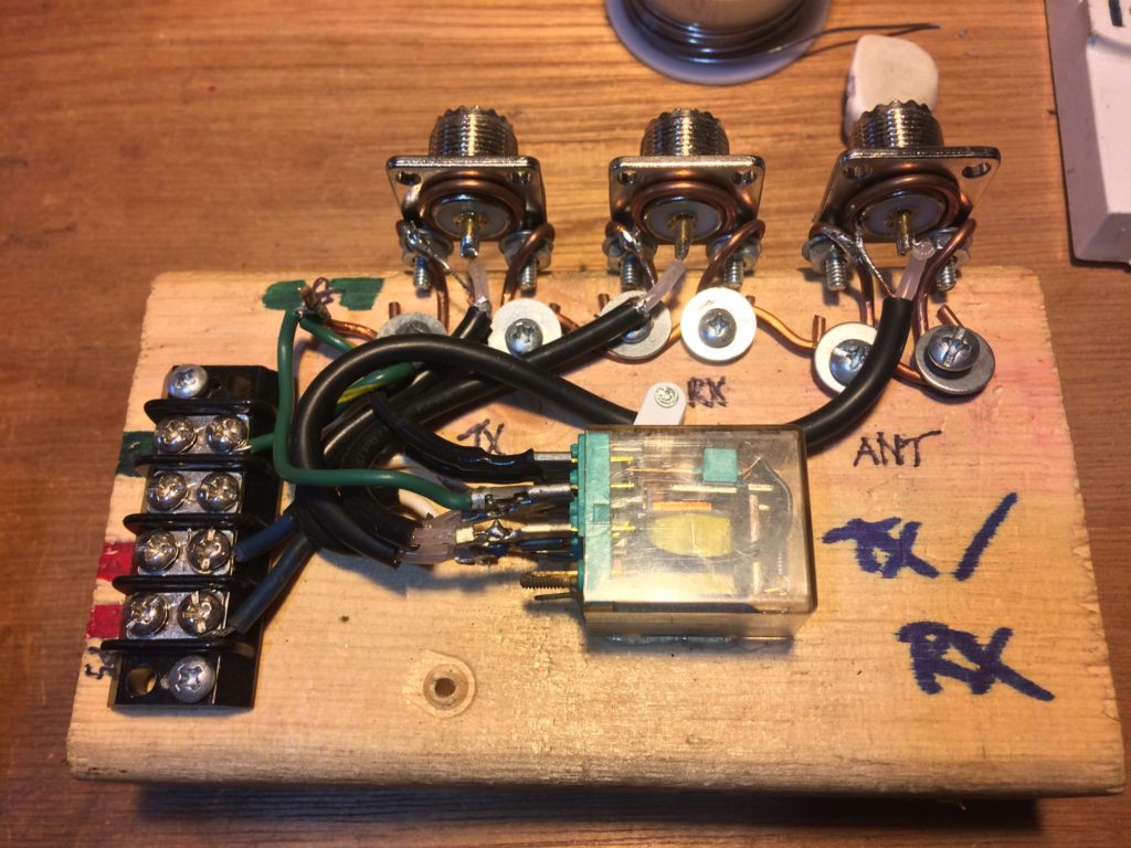
The problem lies between the component in the photo above, the transmitter, and the one in the photo below, the tx/rx switching relay. This was empirically demonstrated for me when I removed the transmitter from the antenna system, which includes a hefty dummy load, and focused on the two power sources that travel between the transmitter and the switching system. Those two systems are the 110 volt house current/voltage that activates the relay coil, and the high voltage DC plate voltage (called B+ for more than a century) that is switched on and off by the relay. The two systems were closest together at the front panel of the transmitter, where the coil was operated by the transmit switch or the remote transmit jack, which interfaced with the VFO. With the AC disconnected, the transmission was clean and noise-free. Unfortunately, without activating the coil, there is no easy way to discover whether the approximately four foot run of the B+ is problematic. But with the AC in proximity to the transmitter, Bob Heil’s circuit, as described, won’t work in this installation. Perhaps he has his tx/rx switch much closer to his transmitter, and he is keeping it isolated from the transmitter’s circuit better than I am able to. In any case, I am going to use a relay with 12 volt DC coil to accomplish tx/rx switching. I must wait for that part to arrive.
So there will be a third installment…