Every word in that title richly deserves the sanitary quotation marks. It’s not really ‘my’ monster. It’s Bob Heil’s monster. It’s not really ‘alive.’ It’s radio gear. And, of course, it’s not a ‘monster.’ It’s a QRP (‘reduced power,’ or ‘low power’) rig.
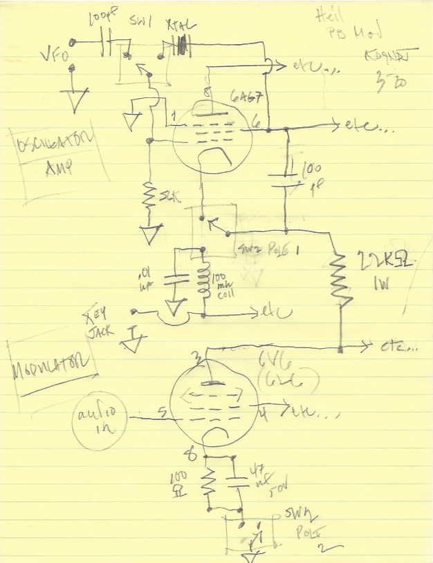
So with those caveats, let me say that the goal of these mods to the Heil Pine Board Transmitter, known hereafter at the HPB or just PB (’cause we Hams LOVE out acronyms!), is to furnish it with a key jack to cathode that also switches off the 6V6 modulator, and to add a VFO input that preserves the topology of the oscillator.
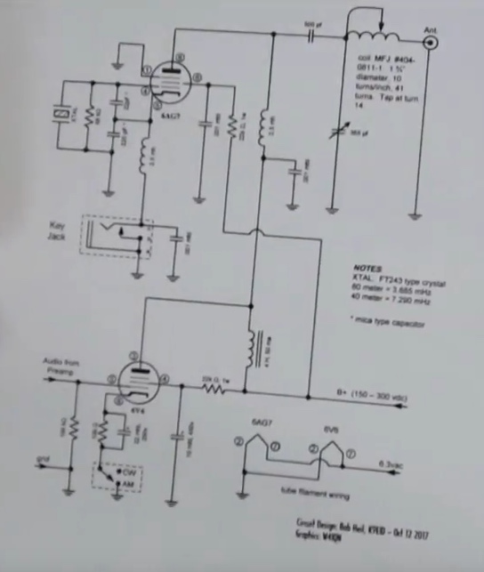
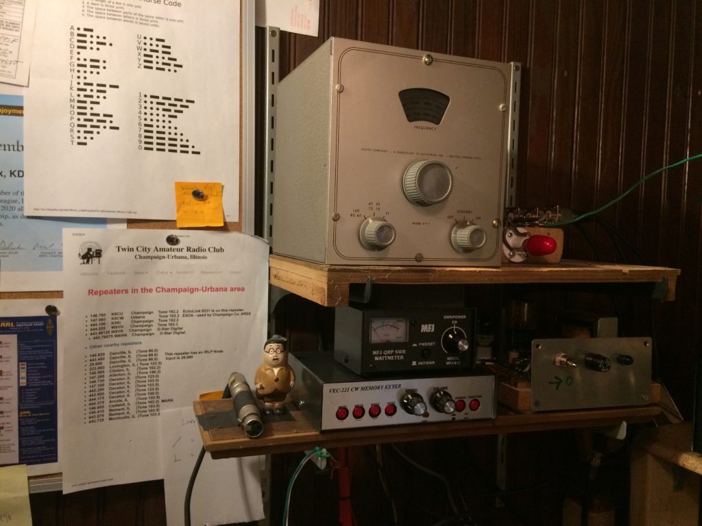
The schematic for this transmitter appeared in ARRL’s QST magazine in, I believe, the February of 2018 issue. Until this link goes bad and I become aware of it, I’ll refrain from reproducing the schematic here. The transmitter uses a 6AG7 vacuum tube as an oscillator and ‘amp,’ (ie, there is no amp; QRP-style, the output goes directly to the matching network and antenna), so the whole thing is ‘the tank.’ A 6V6 tube is specified as the AM modulator. I’ve used a 6L6GC without issue. It’s a very forgiving and fun-loving circuit. Keep adding B plus and you keep adding watts. To a point, of course. Exceed the point, and I assume you start adding smoke. The article mentions this feature: “the only coupling between the oscillator and the load is through the stream of the 6AG7.” The screen grid serves as the ‘plate,’ and the control grid is grounded through a 56k ohm resistor. Heil calls this ‘electron coupling.’ I call it a ‘floating’ topology. The heated cathode is beaming electrons to the plate as usual. The action (oscillation) that is happening in the electron cloud is initiated and sustained by two of the grids and, of course, the crystal. The suppressor grid is grounded.
In a video on youtube as part of the Ham Nation channel, at about 3′:50″, Bob flashes a schematic for adding a VFO (in lieu of the crystal), but the topology of this schematic does not match the above description. This screenshot, I’ll post. It takes some considerable digging to find it:
Here goody number one that I want to add is shown (the key jack), but a) the photo is blurred, and b) we’ve abandoned the ‘floating’ topology. So, if we go with this approach, we have to rewire the transmitter and give up whatever advantage we got from the ‘float.’ (To paraphrase Heil: ‘oscillator frequency stability.’) And, because we can’t read the component values, we have to guess. How much smoke are we willing to tolerate? In the service of what will the smoke be wafted?
And though this simplifies the addition of the VFO (goody number two), since there are plenty of grounded cathode VFO circuits available on the web, there is in fact a website that shows the way. This is the website of WB4WHH, Claude in Virginia. His site has a few of the usual crystal oscillator transmitters, a 6AG7 version and even a 6L6, but his combo of the 6AG7 as an oscillator and the 6L6 as an amplifier uses the floating topology we’ve already built, AND includes BOTH a keyjack AND a switchable VFO/crystal. Hallelujah.
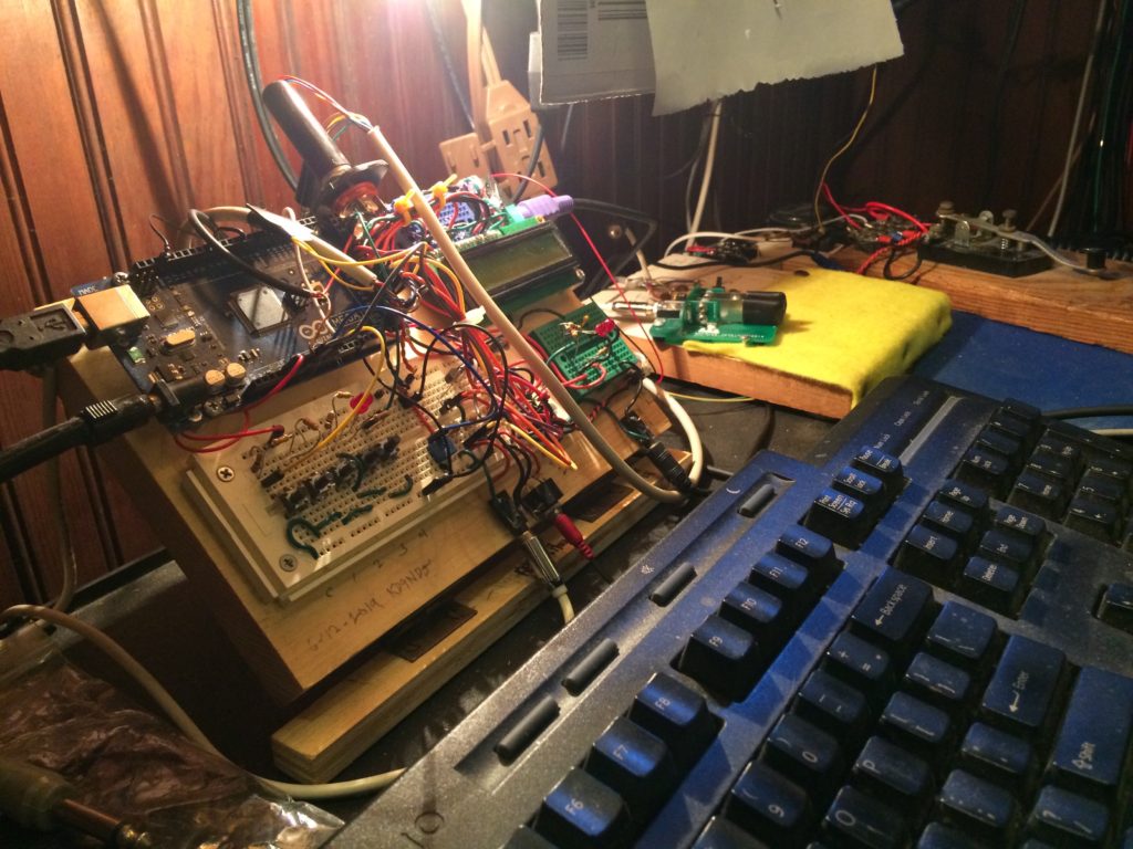
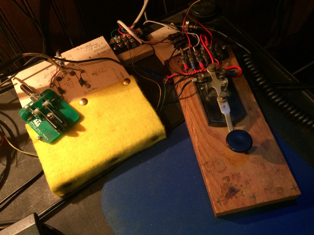
So I mashed all this up, with a crude bunch of schematic printouts and notes, some spare parts (caps, switches, and a coil), and I grabbed a soldering iron and just did it.
In the end, it looked like this:
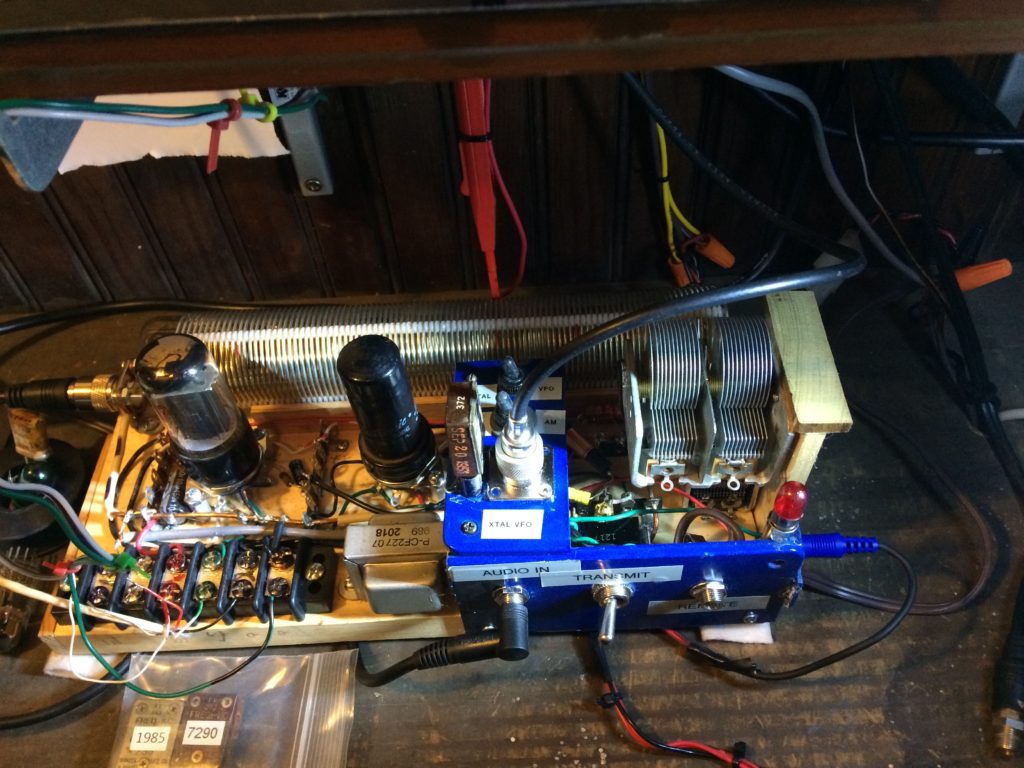
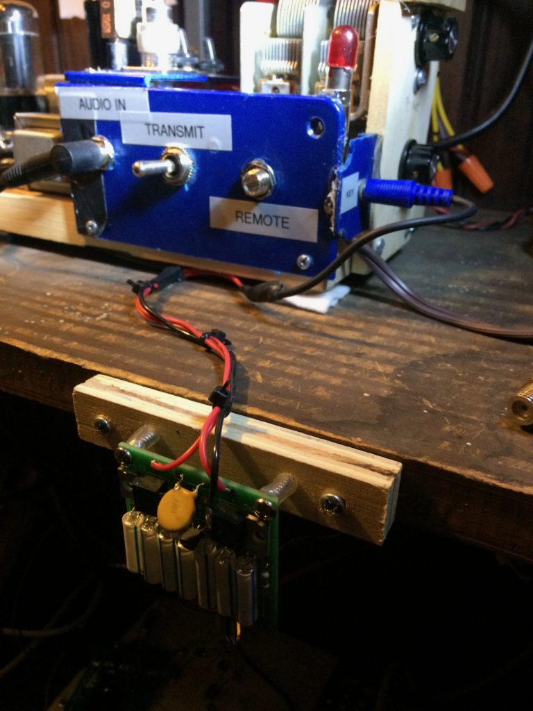
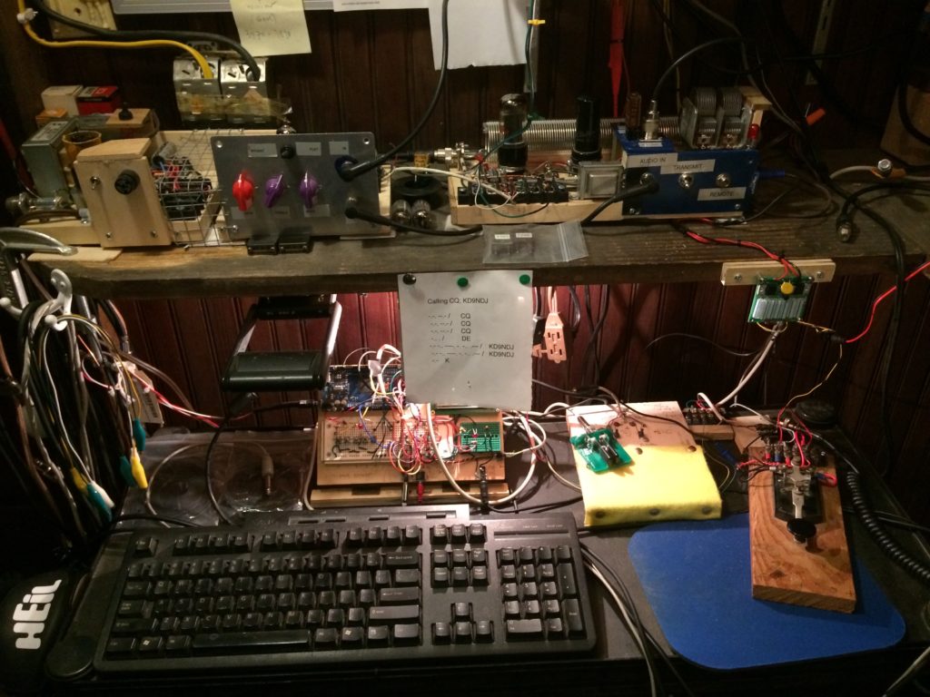
It works, but…
Stay tuned.