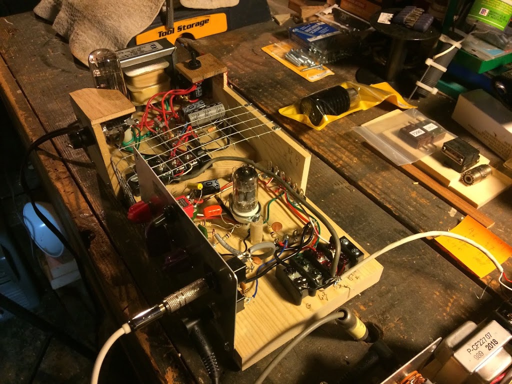
1. AM broadcast band transmitter (kit from Antique Electronics Supply)…
Start here. It is allegedly based on a Zenith wireless record player from the ’40s. It expects a crystal phono cartridge, so using it with line level signals requires a preamp. I’ve built enough of those to have ’em laying around in boxes…
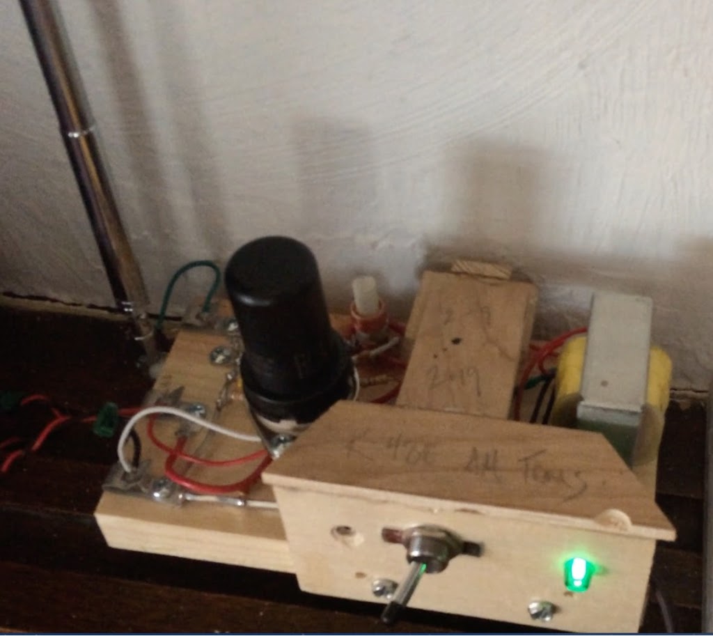
The result is ok. It is tuned to 1150 khz (ie., 1.15 mhz.). It has a 120 cycle hum when the receiver is capable of reproducing it. Some are, some aren’t around here. The hum remains steady in level beneath the signal, so boosting the signal to lower the noise floor is an effective enough solution. It plays just fine through the ’48 Philco. The two units share a room. I modded the transmitter with an antenna fished out of the scrap pile. I used a bit of wire initially, but I get better radiation with the pole, needless to say…
Built with scrap wood over the high voltage areas.
Worked without error on power up.
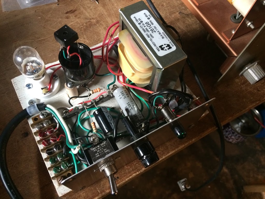
2. Power supply to replace batteries in farm radios… (kit from Antique Electronics Supply)…
It’s putting out about 10 volts less power on B+ than it says it should. Don’t think it’s a wiring error. No matter, it has plenty of output points for B+. C+ I’m not using, but it’s variable. Filament (A+) is also variable. So I’m using it to power …
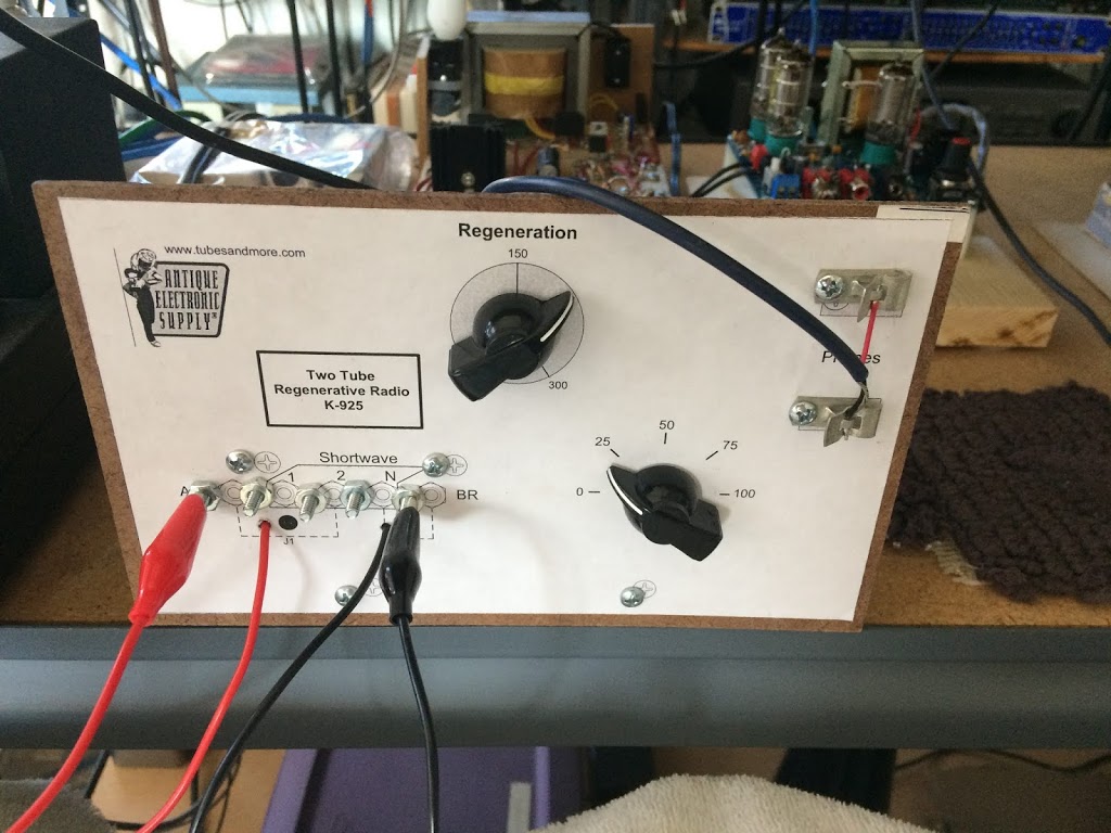
3. 2 tube regenerative receiver… (kit from Antique Electronics Supply)…
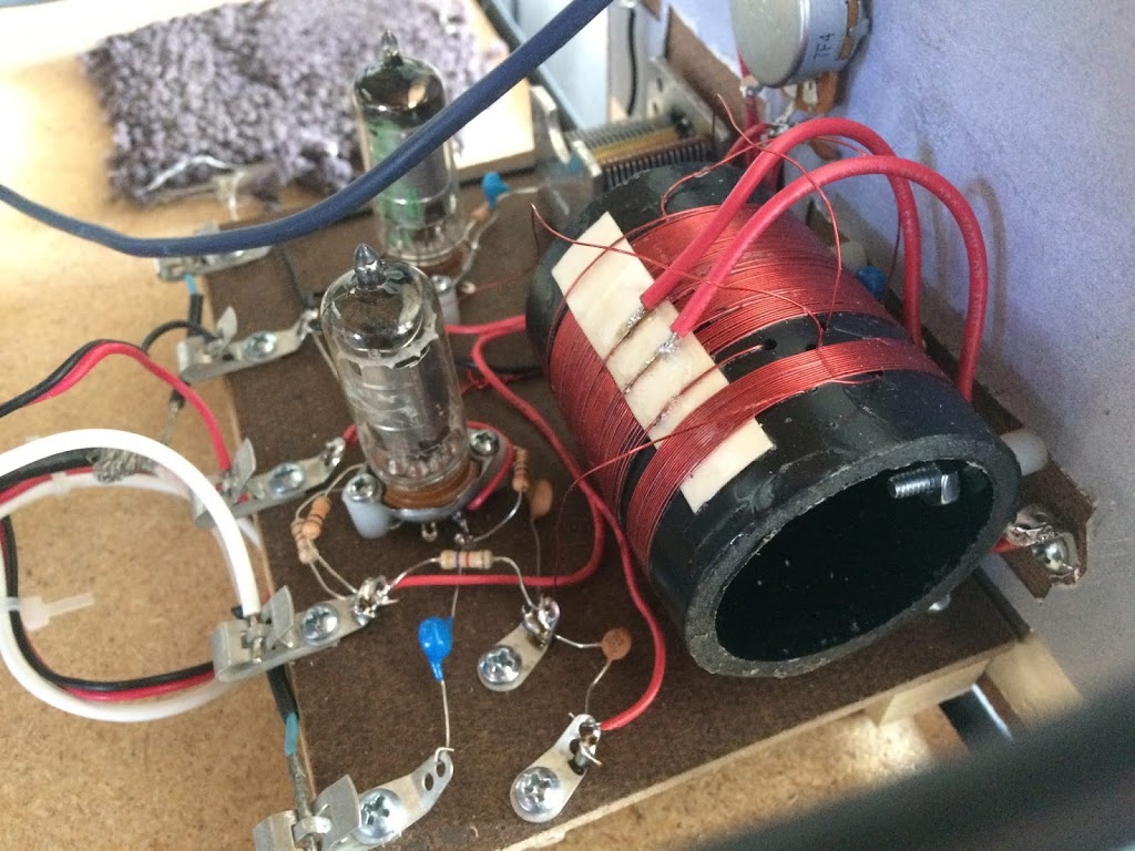 |
| Backside… |
Winding the coil was a royal pain in the ass. The regen radio thing is interesting because you have to actually resonate the coil to tune something in. Very sensitive to time of day, atmospheric conditions, and, apparently, its mood…
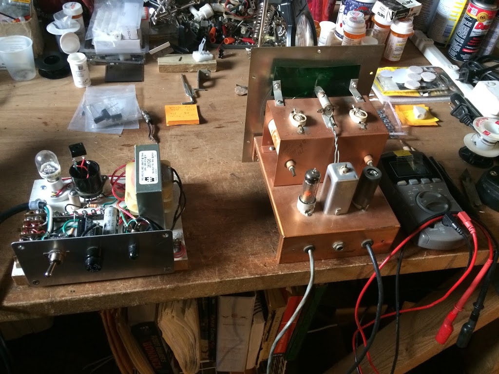
But such as it is, it worked on the 1st try. As did the power supply. Both are used together, as intended.
4. The set of kits from AES that support Bob Heil’s “Pine Board Project.”
There are three kits in the series:
a.) The power supply.
I built this in two versions, and the one from the kit explored both options, both the 6X5 tube version and the full wave bridge rectifier IC version. The one I built by deconstructing Dad’s own pine board power supply (for his Heathkit VF-1), using essentially only the board as it turned out, used only the IC.
The Heil kits (from Antique Electronics Supply) were shy a few parts. A cap here, a few special order items there. The power supply kit came with the tube, though not the IC. It came with the resistors necessary for the 1st version (three filter caps), though not the 2nd ‘two filter cap’ version. It came with the resistors for the IC version, but, again, not the IC.
b.) The preamp.
I had a spare 12AX7. No tube came with the kit.
This is the best kit in the series. It is brilliant and it sounds great. Mine worked on the 1st try.
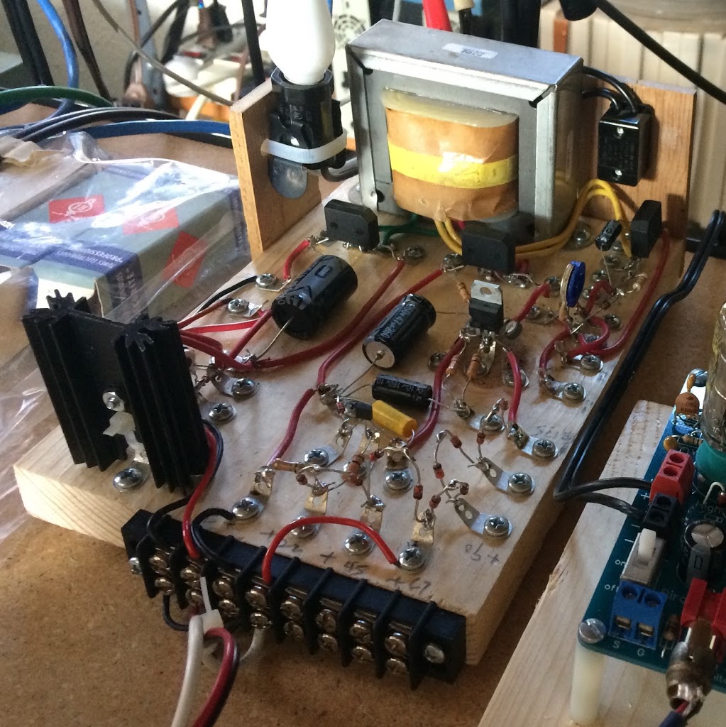
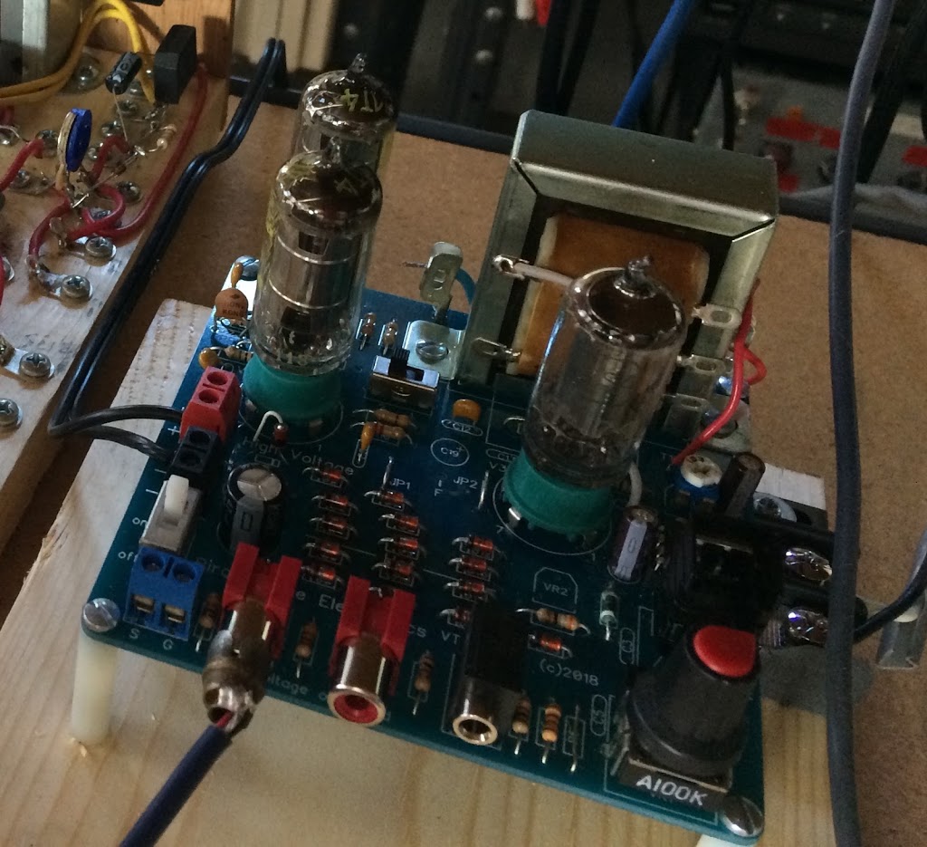
 |
| Power Supply and Preamp |
c.) The transmitter.
Here I was at sea. I had the (mistaken) idea that this was something other than what it was. It was called “AM Transmitter Kit” at AES, and that is indeed true. I lost sight of the fact that it was AM on the amateur bands (40, 80, 160 meters respectively, crystal up accordingly). Getting it down to the broadcast band, ie., below 7.2 mhz, would take more coil and different variable caps. It would also be, uh, illegal at maybe 5 watts and who knows what band width. I have yet to look at its output on the software defined receiver. Having bought the kit, I built it. I crystalled up. I also needed a QRP SWR/watt meter, and a dummy load with a lamp. Bob’s got all that gear on display in his videos.
Versioning is kind of a mess on the Heil site, but that may well be part of the lesson: you have to actually think it through and get a grip on what the videos tell you and what it is you’re doing. This is much more interesting than slapping together a kit of parts. Although, it’s kind of funny to say: “this is a kit of parts missing some items and aiming at the construction of several versions of the circuit without clear instructions on the versions and reasons for the re-thinks.” The videos express how easy it is to find the parts. This is generally true; you can find the parts. But some of the parts came from sources requiring a minimum order. By the time I was done, I spent maybe $400 on the project. There are cheaper ways, but the time spent winding a coil, for example, was just not available to me at this point in my life. And there was no way to get the 2.5 mh choke without a minimum order of $$$. Just sayin’. (Bitch, bitch, bitch.)
All in all, though… I had more fun than I’ve had building in a while.
Getting the transmitter up was a two week troubleshooting adventure, neatly undoing my pride at my string of successes with 1-4b. Keep in mind that I was a bit slow figuring out what this design was actually meant to do. With a lamp, a watt meter, and a dummy load, I spent some time firing it up and scratching my head. It passed “the smoke test,” which was Dad’s expression for plugging it in, turning it on, and looking for smoke. But nothing appeared on the meter, and the lamp indicating output refused to glow.
Out came the schematic and the digital multi-meter (DMM). I discovered that my mounting screws shorted out the open air tuning capacitor. That brought much of the circuit to ground, so it could not actually resonate the coil. I solved that problem, but still nothing could get that lamp to glow. So? Well, among Dad’s kit was a “Grid Dip Meter.” ? ? ? … The grid dip meter came with a box of plug in coils, one for each of about 9 frequency bands. That device allowed me to tune up the coil in my transmitter. Sure enough, when the GDM (and this transmitter actually has a grid!) was indicating max resonance, the light and the watt meter responded. My monster was alive, at long last. As it turns out, it takes a moment for the lamp and light to respond. Once it was putting out a signal, I plugged in a little walkman-type radio and transmitted that to a variety of receivers I have around, including the Collins 75A-1.
5. The 3 tube version of an amp from Pirate Pete.
This was intended to be a complete kit with a blank PC board. It was also missing parts. My parts stash was able to make up the deficiency. The 1T4 x2, 3S4 topology matches the 1T4 x2 topology of the AES regenerative above. It was kind of an impulse item, but it was a worthwhile build.
6. A second high output version of the Heil pine board power supply.
I decided to re-work one of Dad’s pine board projects. This was a power supply for the Heathkit VF-1 variable frequency oscillator. In theory, if the VF-1 can be brought back to life, I can plug it in to the Heil transmitter and not be stuck to the frequencies I have crystals for. (I am, as they say, “rock bound.” Hams are funny folks. And yes, I could use an Elmer. My father is, unfortunately, dead.) Here’s Dad’s board. It’s not a great photo; it was taken so that I could recall what went where after I tore it apart.
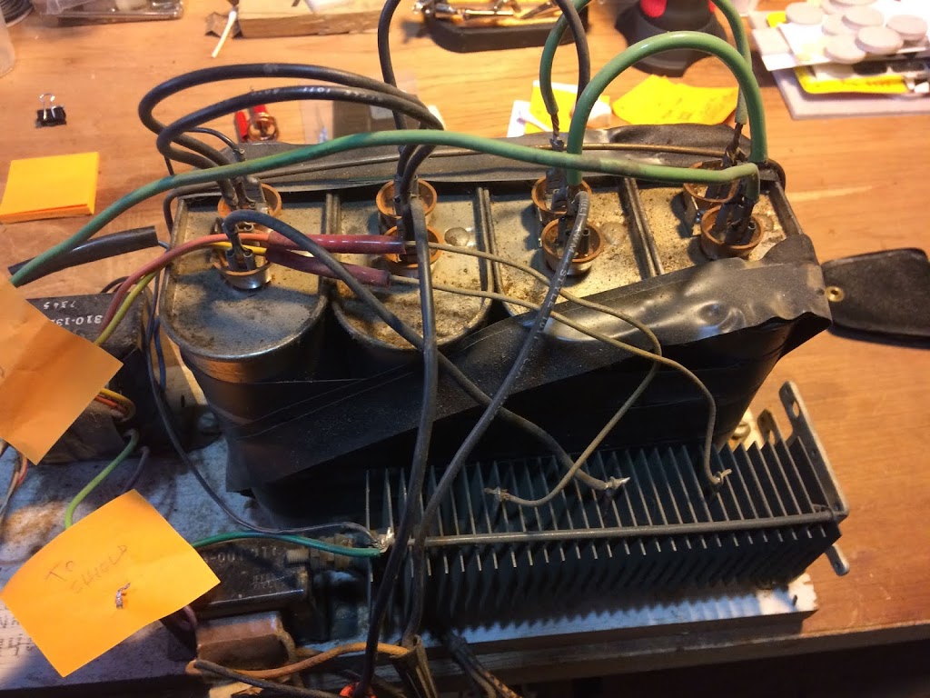 |
| Top View |
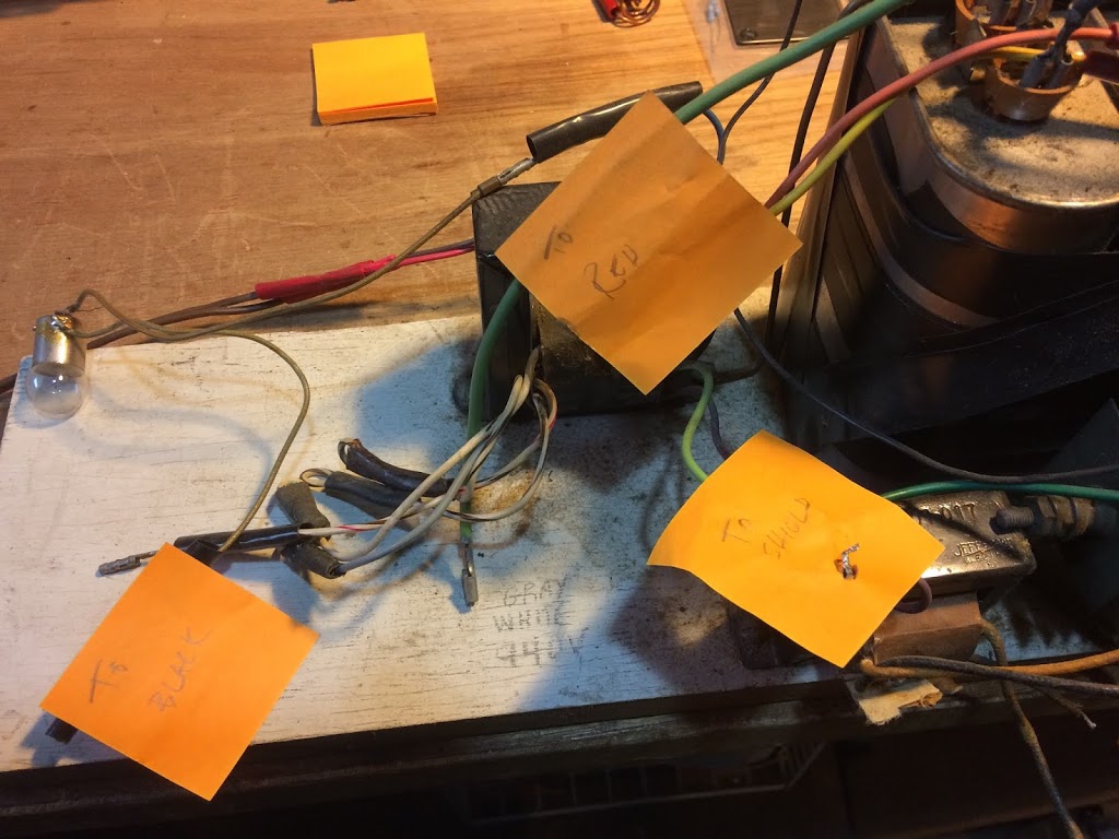 |
| Connections, including to filament, in series with lamp… |
So I then took Dad’s work off the board and sawed a piece off…
I had hopes of using the transformer, but after measuring out the lead combinations, I had only two useful voltages, and one was not all that useful. I could get 250 volts on on secondary, but filament voltage had to be cut in half, as I had a choice of 10 or 13 volts. So this transformer would do for a 12 volt filament with a 200-300 hundred volt B+. A 12AX7 preamp, for example. But not really for the VF-1. Dad, as one can see, lit the filaments by running the voltage in series with an automotive lamp. I built it this way in my re-work, but the result was 7 volts or so, a bit high for a 6.3 volt filament.
I broke down and bought another Hammond transformer…
 |
| On |
 |
| … and… VH-1 minus case. |
The resulting circuit puts out a neat 400 volts DC. That might be a bit high for the VF-1. Have to investigate the VF-1 info. Schematics are readily available…